The Evolution of Modems
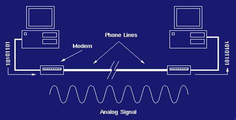
What is a modem? Modems are used more often than most of imagine. For us techies, we are always using one and understand their complexity, but for the average user they do not realize modems are so widely used. If you own a personal computer, ever used a fax machine, ATM machine, or even simply used a credit card or bank card. All these devices in some form utilize the power of a modem. The modem originated from the need of modulation and demodulation, hence its name: a modem. A modem in the traditional since is a device that transfers information, weather it be data, voice, video, or many other types, from one place to another utilizing a standard phone wires. Originally this was the main source of medium for the modems. The phone lines, which are analog in nature, require the signal to be sent in a sound wave. The modem comes into play to convert the message or digital language into an analog signal appropriate for the phone line medium, but its job is not done here. It must also receive the analog signals and translate it into the digital language for the computer or device to understand. For all Internet and communication dependent users out there the little modem is an extremely important necessity.
The computer itself came about during World War II and was widely used by the Germans on war efforts and codes. In the late 50s, computers came more widely available, not on the personal level as today, but for large business. These computers were extremely large and required a lot of physical space, not to mention processing time was crucial and hard to come buy. This inconvenience brought about the need for networks. So, the processing can be spread over multiple computers in different locations.
In the late 60s, the use of phone lines for data transfer became popular. It was an amazing break through for computer processing and the modems became a curtail part of every machine. Granted the speeds of these original modems like the Bell modem it seems terrible for today�s standards. For example here are some of the original speeds over the years.
The History of Modem Speeds |
|
|
300 bps |
1960s through 1983 |
|
1,200 bps |
1984 and 1985 |
|
2,400 bps |
Late 80s |
|
9,600 bps |
Early 1991 |
|
19,200 - 33,600 bps |
Mid 1992 - 1997 |
|
56,000 bps |
Phone line standard, appeared in 1998 |
|
10,000,000 bps |
ADSL, appearing in 1999. |
As you can see the transfer rate modems use as a standard are rapidly changing. The red text indicates the maximum rate using traditional phone lines as a medium, which is actually more realistically approximately 53,000 bps. The blue text in the chart indicates the latest advancement in modem technology. These modems utilize a new medium, weather it be cable, coaxial, or a finer medium. The new mediums allow a much greater bandwidth and in turn a faster transfer rate. Modems are rapidly evolving to handle faster and faster loads, but this is no easy task. The actual bandwidth for a fiber optical cable is no even close to being maximized, like the phone lines. Viewing the above history of modem speeds it is hard to believe that it was so slow, but one must realize that the original intent of the modem was to communicate text data using software like Telnet. Today�s high demands of video streaming, graphics, sounds, requires a much faster transmission rate to make it convenient and practical.
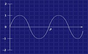
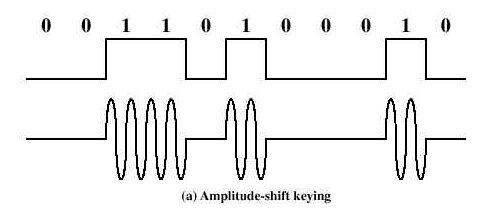
To begin to talk about how modems work: communicate, modulate and demodulate, we must first understand some terminology and certain aspects about data communication. We all know data is communicated in some form of binary numbering or code. This binary code takes the form of only 1�s and 0�s, each representing a different level in the frequency. Most of us are familiar with the term bps (bites per second) when talking about the transmission speed of a modem, but the baud is a more important term when talking about modems themselves. The baud although similar is not the same. The number of signal intervals that are transmitted during one baud or pulse characterizes the carrier signal. This is a key idea since in with the current medians available today for most users there is a max limit of transmission. The idea is to the modem designers is to pack as many bits into on baud as possible. Meaning put more data bits in each bit. This will in turn allow for a higher overall speed. For example a modem running at speeds capable of 9600bps transmit at only 1200 baud, but it is cramming 8 bits into each baud frame. We can now talk about the actual modulation. The above concept of packing as many bits into a baud is know as quadrature amplitude modulation, which is based on the signal�s amplitude modulation. For example here is a typical sign wave. Each protocol is different, but most techniques will use the 1v of the wave to represent a digital 1, and the negative end of the curve to represent a digital 0.
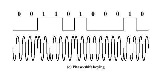
Over a transmission these waves can be amplified to generate a longer traveling signal. This can at times cause the distortion in the signal to also be amplified, which will distort the signal. It is the modem that must translate and error checks these signals. In this technique only the amplitude is changing, meaning that the amplitude is what determines the signals value. There are many other techniques such as Phase shifting, and QAM (a combination of the two).
Utilizing these different digital to analog and analog to digital conversions modems have progressed to where we are today and will continue to change and progress to faster and more efficient techniques of modulation and demodulation. The modem itself is a rather simple device that converts signals that travel over a medium like the phone lines. New technologies in medium types and the introduction and growth of DSL/ADSL and other cable type connection are redefining the modem market with a new door of boundless opportunities in growth and advancement.
With the increasing use of modems to link computers and to access them remotely, protocols and standards had to be developed to allow modems and other hardware components made by different manufacturers able to communicate with each other. Without these standards, it would be impossible for computers to understand a message sent by another computer. Two organizations accepted the challenge to create modem standards: Bell Labs and the ITU-T. Bell Labs developed the first commercial modems in the late 1960�s and early 1970�s. They defined the development of this new technology and instituted many defacto standards that are still followed by many manufacturers today. To better understand the characteristics and specifications of modems, let�s look at the standards created by Bell Labs. The following standards will be discussed in increasing order of their data transmission rate (bps).
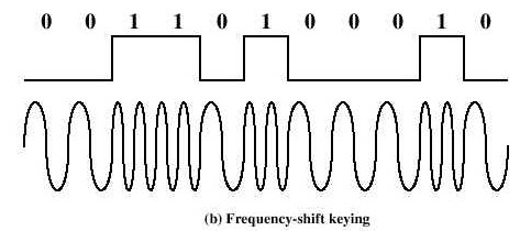
Bell labs developed the first modem standard by issuing the 103/113 series of modems. Data transmission is asynchronous, using FSK modulation. 300 bps is the highest rate of transmission possible. To put a message on the line, the frequencies of 1070 Hz and 1270 Hz are used to represent 0 and 1 respectively. To answer this signal or message, the frequencies of 2025 Hz and 2225 Hz are used to represent 0 and 1. Be it as it may that this standard isn�t sufficient for today�s standards, 300 bps is the ideal transmission rate for low demand users who exchange files or access local bulletin boards.
The next set of standards to be discussed is the 202 series. These modems are very unique because they have two transmission frequencies. Both frequencies operate in half-duplex over two-wire telephone lines and transmission is asynchronous. The first frequency operates in one direction between 600 Hz and 3000 Hz and uses FSK modulation. The second transmission frequency operates in both directions at 387 Hz, uses ASK modulation, and transmits data at a rate of 5 bps, which is used by the receiving device to communicate with the sender, to regulate the flow of data, and to notify the sender that a frame needs to be resent due to errors.
The first set of modems to be developed with two speeds was the 212 series. Both speeds operate over two-wire switched telephone lines in full-duplex mode. The slower of the two speeds, 300 bps, uses FSK modulation and data transmission is asynchronous. The higher of the two speeds, 1200 bps, uses 4-PSK modulation and data transmission is synchronous or asynchronous. The 212 series is virtually the same as the 202 series but with a few minor modifications. Both the 202 and 212 series can transmit data at a rate of 1200 bps, but the 212 series achieves this in full-duplex as opposed to half-duplex by the 202 series. Also, the 212 series uses PSK modulation as opposed the FSK modulation used by the 202 series. By using PSK, data transmission is more efficient. The last improvement by the 212 series on the 202 series pertains to the direction of transmission. In the 202 series, two frequencies are used to send different bits in one direction, but in the 212 series, two frequencies are used to send different bits in two different directions. This is accomplished by each phase shift representing two bits.
Next, let�s look at the 201 series that improved the data rate from 1200 bps to 2400 bps. The interesting aspect of this series is that they may operate in either half-duplex mode over two-wire switched lines or full-duplex over four-wire leased lines. Data transmission is synchronous and uses 4-PSK modulations. This means that only one frequency is needed for transmission over a pair of wires. By splitting the directions of transmission into two separate pairs of lines, each direction of transmission is able to use the entire bandwidth of the line. And by allowing the usage of the entire bandwidth of a pair of lines, the data rate is doubled to 2400 bps in both half-duplex and full-duplex modes. The 201 series modems are commonly used by many businesses in terminal-to-host, multidrop applications.
To even further improve on the 201 series, Bell Labs created the 208 series. The 208 series modems uses 8-PSK modulation, transmission is synchronous, and they operate in full-duplex mode over four-wire leased lines. Full duplex operation is achieved in the 208 series the same way it is achieved in the 201 series; by doubling the number of wires for transmission and dedicating each pair of lines to each direction of transmission. The main difference between the 201 and 208 series is that the 208 series uses 8 phase shifts to represent data. This allows three bits per baud, which results in a transmission rate of 4800 bps.
The last standard but the first series developed by Bell Labs to improve the data transmission rate by combining ASK and PSK modulation was the 209 series. This series of modem uses 16 QAM modulation operates in full-duplex mode over four-wire leased lines, and transmission is synchronous. By using QAM, which uses PSK, each phase shift represents 4 bits. At the rate of 4 bits per baud this improves the data rate to 9600 bps. Just like the 201 and 208 series, full duplex operation is achieved by doubling the number of wires so each direction of transmission has a channel to itself.
It is important to remember that Bell Labs paved the way for modem standards, but with the internet in high use and technology growing rapidly, we needed faster more, efficient modems to handle data. Today, many of the modems that are in use carry the standards set forth by the ITU-T (International Telecommunications Union-Telecommunications Sector). For the purposes of explaining the ITU-T standards, the standards will be broken into two sections: those that are identical to Bell modem standards and those that aren�t.
For every modem standard created by Bell Labs, the ITU-T has an identical standard. The ITU-T V.21 series is identical to Bell�s 103/113 series. Also, the V.22, V.23, V.26, V.27, and V.29 series are identical to the 212, 202, 201, 208, and 209 series created by Bell Labs. Let�s now move onto the standards that improved on the Bell Lab�s series of modem standards.
The first modem standard developed by the ITU-T that was totally different than any standard created by Bell Labs was the V.22bis series. This standard is the second generation standard of the V.22 series. This modem can operate at two speeds: 1200 bps or 2400 bps. The speed at which it operates depends on the speed of the other device in the exchange. If the modem on the other end transmits data at 1200 bps, it will receive data at 1200 bps. The same goes for 2400 bps. By changing its speed based on the other modem�s speed is how this standard achieves compatibility with other modems. If the modem operates at 1200 bps, 4-DPSK modulation (Differential Phase Shift Keying) or two bits per phase change is used at 600 baud. At the rate of 2400 bps, 16-QAM or 4 bits per baud are used to modulate data at 600 baud.
The next ITU-T standard to be discussed is the V.32 series. It is an improvement on the V.29 series that uses 32-QAM Trellis-Coded Modulation. Trellis-Coded Modulation is basically QAM but transmits a redundant bit with each bit section. In the V.32 series, the data stream is broken up into 4 bits, but 5 bits are sent due to the redundant bit. This bit is calculated based on the values of bits in each 4-bit section. By adding this redundant bit, the receiver is less likely to misread the signal due to distortion and noise that has altered the signal. In essence, the trellis facility provides error detection and correction. At a baud rate of 2400 with 4 bits per baud, the V.32 series is able to transmit data at a rate of 9600 bps.
The second generation of the V.32 modems, V.32bis, was the first modem standard to achieve data transmission at a rate of 14,400 bps. This bit rate is achieved by using 64-QAM at six bits per 2400 baud. Just like the V.29 series, the V.32bis series is able to change its transmission speed based on the quality of the line and/or signal.
To further improve on the V.32 series, the ITU-T developed the V.32terbo standard. This standard is the third generation of the V.32 series. The only enhancement provided by this standard is its use of 256-QAM. 256-QAM transmits 8 bits per 2400 baud, resulting in a bit rate of 19,200 bps.
The next series, the V.33 series, is also loosely based on the V.32 series. The V.33 series uses 128-QAM at 2400 baud as opposed to V.32�s 64-QAM at 2400 baud. Each baud transmitted contains 6 bits per baud plus 1 redundant bit that allows 7 bits per baud to be transmitted. By transmitting more bits per baud, the V.33 series achieves greater efficiency in error detection and correction than the V.32 series.
To even further improve on the bit rate of the V.33 series, the ITU-T developed the V.34 series. This series uses 4096-QAM to transmit 12 bits per 2400 baud to achieve the bit rate of 28,800 bps. The V.34 series is the first standard to provide data compression. By adding data compression, this series is able to transmit data at a rate up to 33,600 bps.
Not only has the ITU-T developed standards for data transmission, but they have also developed the V.42 series to define error correction and data transmission. The V.42 standard uses a protocol called Link Access Procedure for Modems (LAPM) at the data link layer for error correction and detection. The second generation of the V.42 series, V.42bis, defines data compression using the Lempel-Ziv-Welch compression method. By using this standard, modems can achieve a compression ratio from 3:1 to 4:1. By compressing data, the sender can send more bits during a predefined period of time.
Studying the standards developed by Bell Labs and the ITU-T is very important, but it is also important to realize that very shortly these standards can become obsolete. The latest standard developed by the ITU-T pertains to the V.90 series. This standard allows data transmission up to 56,000 bps, but with the introduction of Cable modems and DSL we will be able to send and retrieve data faster and more efficiently.
DSL Overview:
DSL (Digital Subscriber Line) is used today to refer in general to a family of High-speed data transfer standards: HDSL, SDSL, ADSL, RADSL, and VDSL. This transfer median makes use of the available high frequency portion of the bandwidth of existing telephone lines-the local loop to accomplish high-speed delivery of data, voice and multimedia. The �local loop� refers to the twisted-pair-wire telephone line that forms the loop from the telephone company-to the residence and returns to the telephone company. Originally this copper wire loop was designed to support POTS (Plain Old Telephone Service) to the residence using two wires per phone line. There are problems with DSL and the characteristics of the local loops, which limit the area that DSL based technology can serve. This limitation is a combination of the analog nature of local loops and the some of the changes to the design of local loops in the 1980�s that were brought about by rapid expansion of POTS due to population growth.
DSL can carry both voices for POTS and data simultaneously/independently. The DSL data transfer/receive capability is continuously connected, which differs from Modem-Telephone operations that must establish a connection prior to data transfer and require exclusive access to the phone line. DSL further differs from MODEM operations in that DSL transmits a digital signal over the local loop. Modems convert the signal from the computer to analog prior to transmitting upstream on the local loop. The telephone company conversely converts digital signals to analog prior to transmitting downstream via the local loop and conversely converts the analog signal received from the local loop to digital. Normal modem operations are limited to 56 Kbs and IDSN (another MODULATE-DEMODULATE based technology) achieves 126 Kbs only through using two-phone lines and transmitting 56Kbs times two.
The major bandwidth bottleneck for modems is the analog-based transmissions through the loop. DSL speed (closely related to signal strength/quality) is dependent on the proximity to the phone company and in general is 50 times faster than modems. Rates for DSL promise to be as high as 6.1 mbps (out of a theoretical 8.448 mbs) supporting continuous transmission of video, audio and 3 D effects. Average DSL speeds will probable be closer to 512 Kbps to 1.544 Mbps downstream and 128 Kbps upstream.
A practical comparison would be the CNN online Home Page that is currently 69K (excluding graphics or advertisements). This is 69x1024 characters� in size.
The transfer time for a 56K modem would be approximately 13 seconds. This does not account for the time required for the initial �fetch� request to reach CNN, then for the CNN server to respond, the reply back then the additional requests, starts, and completes for all the images.
In contrast, a 416 K SDSL link would load the CNN home page in approximately 2-4 seconds, including all the images and a 7.4 Mbs ADSL link is faster (but at this stage the speed of the users system-browser and computer becomes the limiting factor).
Another factor to consider is the overhead involved with the exchange of data packets. The time required for a single packet of information to travel to a remote server and return to the sender is referred to as latency or ping time. Latency is also affected by the number of hops between sender and receiver, network congestion, etc. Improvements in latency are related proportionally to line speed (which is dependent on bandwidth). Analog modems add a ping time of 10 ms to 1 second depending on the size of the data packet while DSL modems add 7 -70ms. For comparison, a worst-case scenario has Analog modems needing �th of a second while DSL needs 0.07 second. This transfer rate difference is most apparent in the interactive-gaming environment where DSL will provide game play relatively free of jittering, freezes, hops, and the quake POD (ping of death).
Coaxial Cable promises a bandwidth of 870 MHZ (Mediacom) and some systems can provide up to 10 Mbps, while customers will see a more realistic figure of 1.5 Mbps. This transfer rate is faster than most of the DSL capabilities and is 100 times faster than a standard modem. But the primary drawback for cable is the expected degradation of performance as more customers are added to the system. The operation of the data transfer on cable is similar to a LAN in that as more customers are connected to the net, the system performance-specifically speed, proportionally decreases. Another concern is the impacts on overall signal quality as more households plug-in and connect more devices (TV, phone-local and long distance, Video-On-Demand, etc.).
The upstream bandwidth is also considered to be prone to RF interference and limited in capacity. These transmissions may also have to compete with others on the system resulting in high latency. It is expected that the increase in transmission speeds will in-turn increase the internet gaming arena and will place a greater demand on upstream utilization which cable upstream operations may not be able to support. Currently, cable modems have a customer base with a 5 to 1 lead over DSL. It is expected that once the customer has invested in a cable system (with home wiring, cable modem, installed software, relationship with an ISP, etc...) it is doubtful that even lower rates offered by DSL will entice the customers to switch. The cost of a cable modem is about $300 and the monthly fee is approximately $40, which is comparable to DSL. The major problem facing cable companies will be converting their facilities to a two-way plant.
One additional problem for cable customers may be the restriction on the use of bandwidth intensive applications. Cable users may not be allowed to telecommute, host web sites, use video teleconferencing or any other high bandwidth applications. In addition to restrictions on use, there is also a security issue that is the result of the �shared� subscriber line. While DSL offers the security of a dedicated line to the central office, cable lines are vulnerable to data interception, unauthorized monitoring, and hacking from users on the same network.
Fiber is probably the fastest but also most expensive technology today. Current fiber-to-the-home systems give customers the ability to download data at an astonishing 100 Mbps. The major detractor to the use and deployment is cost, which could run $1,500 for initial installation. One of the advantages of this system, other than the high transfer rate, is that the signal quality is not as dependent on distance as the metallic-electrical transmission mediums. Fiber works as well in the rural areas as it does in the more densely populated suburban or urban areas. One other option is to install fiber partway to the user. These systems are referred to as fiber-to-node, fiber-to-cabinet and fiber-to-the-curb. For densely populated areas, the provider may even run fiber to an enclosure to provide service a particular business region or housing subdivision. The optical signals at the fiber terminations are converted to electrical signals that are connected to the customers via metallic cable. In this case the cost can be shared among hundreds of users but the transmission rates are lower that the fiber-to-the-home as the final metallic connections act as bottlenecks. The technique used to multiplex signals from many users is wavelength-division multiplexing which will use a different wavelength or color for each individual signal.
ADSL (Asymmetric Digital Subscriber Line)
Originally developed in 1989 at Bell Lab to support video services over standard copper wires, it is considered to be the primary technology for high-speed Internet applications.
ADSL is based on the assumption that the home-user will be downloading (receiving downstream) more information of a greater complexity that uploading (or sending upstream). To maximize on this assumption, ADSL divides the bandwidth of the twisted-pair/local loop into three separate bands:
Frequency Range Bandwidth (Khz)
POTS 0 � 25 Khz 25
Upstream 25 � 200 Khz 175
Downstream 200-1000Khz 800
The resulting separation allows simultaneous-independent use of voice communication as well as data transmissions.
There are two methods that implement ADSL:
CAP (Carrierless Amplitude-Phase) is similar to QAM but more complex. The other implementation DTM (Discrete Multitone Technique) is a combination of QAM and FDM (Frequency Division Multiplexing). The bandwidth is divided into channels of 4 Khz, each with a discrete carrier frequency.
DTM is standardized by ANSI that requires a rate of 60 Kbps for each channel, which correlates to a QAM modulation of 15 bits per baud. The upstream bandwidth usually supports 25 - 4 Khz channels, which results in a bit rate computed by multiplying the number of channels by the rate per channel. In this case 25 channels times 60 Kbps per channel yields 1.5 Mbps theoretical (actual rate is a factor of local loop characteristics and noise interference, probable rate would be 1.1 mbps). The downstream bandwidth of 800 KHz can support 200 channels which yields a theoretical bit rate of 12 Mbps (but should expect 500 Kbps to 8 Mbps, unless home is close to Central Office).
Common ADSL transfer rates are: 640/90K, 1600/90K, 680/680K.
Local Bell South-FastAccess promises 256K upstream and 1.5 Mbps download.
RADSL (Rate Adaptive Asymmetrical Digital Subscriber Line )
RADSL was developed by Westell and is based on ADSL technology and allows different rates to be assigned to the different transmission media (voice, data, etc..). The FlexCap System allows RADSL to provide from 640Kbps to 2.2 Mbps for downstream transmissions and from 272 Kbps to 1.008 Mbps for upstream transmissions over existing telephone lines.
HDSL (High bit Rate Digital Subscriber Line)
HDSL is the earliest version of the DSL family to be widely used. It primarily services corporate sites by providing wideband digital transmissions within the corporation as well as acting as the communication link to/from the telephone company. Data transfer is symmetrical and as a result the transfer rate is lower than ADSL. The symmetrical transmission fulfills the corporate requirements to send as well as receive large volumes of data.
Using an encoding scheme (2B1Q) , which is not as susceptible to attenuation as T1 lines and provides a data rate of up to 2 Mbps up to a line distance of 3.6 Km without repeaters. T1 uses AMI encoding, the lines are more susceptible to attenuation, deliver approximately 1.5 Mbps and are limited to 1 Km (before repeaters are required).
This technique essentially divides the overall bandwidth in the twisted pair that is approximately 1 Mhz into 256 sub channels of 4Khz each. The result is the same as having 256 modems on the same line. It is important to note that this DSL method does not support simultaneous sue of Voice and data transmission. In this case the entire bandwidth of the line is dedicated to data transmission.
SDSL (Symmetric Digital Subscriber Line)
Uses Technology similar to HDSL to achieve the same performance but uses only one-twisted wire pair. SDSL provides 1.544 Mbps on a duplex line.
VDSL (Very High bit rate Digital Subscriber Line)
This is the fastest data transfer system but is currently used in limited commercial settings. It had been referred to with a variety of names�VASDL, BDSL or even ADSL but in 1995 VDSL became the official title of the standard. In the areas it is used, it provides integrated TV, Phone, and Internet services all down one line from a local fiber connection. (Expect the high cost associated with the required hardware to keep this technology in the �Densely� populated customer service areas�do not expect this compete with the cable company in Lenox in Berrien County. VDSL uses fiber optic, coaxial cable or twisted wire for distances of 300 to 1800 meters/1000 to 4500 feet. With a modulating technique of DMT it provides an upstream rate of 1.5 to 2.5 Mbps rate and downstream of 50 to 55 Mbps. Line distance plays a major role in the downstream speeds� 4,500 ft yields 12.96Mbps, 3,000 ft yields 25.82 Mbps and 1,000 ft yields 51.84 Mbps.
The primary limitation for DSL is a DLC (Digital Loop Carrier), which, the telephone companies started to use in the 1970�s when the focus of the phone companies centered on providing high-quality phone/voice communications. The standard configuration for a DLC multiplexes twenty-four local-loop customer lines onto a single T1 line (or can be HDSL or Fiber Optic) that carries the signals to the Central Office. DLC output line sizes range from 24 to in excess of 1,000 lines. An SLC is AT&T�s version of a DLC and �lightspan� is another term used to describe DLCs. These DLC concentrators were less expensive than the copper loops previously used and were primarily used in the 1980�s, especially in areas of rapid growth.
The basic problem with these legacy DSL systems is the system centers on the designed capability. The DLC uses a sampling rate of the local-loop�s analog signal of 8,000 times/second and converts each sample of the analog signal into its eight-bit digital equivalent. This limits the legacy DSL analog to digital conversion rate to 64kbps (8 K samples/sec multiplied by 8 bits/sample). Additionally the architecture of the �back� of the cabinet, the back plane and the common units, restricts DSL output capacity to that required to support a single T1 line (1.54 Mbps or 64 kbps/circuit x 24 circuits/digroup). These legacy DSL systems outnumber the newer-DSL-capable DLCs by four to one. There are three possible solutions to the DSL problem: DSLAMs, ADSL Line-Cards and RAM.
Digital Subscriber Line Access Multiplexer (DSLAM) processes the digital signal from the customer system/equipment. DSLAMs need to be in a controlled environment and are generally installed in the central office but can also be installed in remote locations in �hardened� cabinets. The DSLAM must be split-off from the DLC-bottleneck as the DCL cannot handle the 8 Mbps or even the 1.5 Mbps (see DLC legacy limitations discussed above). In the central office this involves a splitter which routes the analog POTS to the appropriate switching circuitry and the customers digital signal to the DSLAM. Remote DSLAMs are located outside the protective environment of the central office. They are environmentally hardened and placed inside a protective cabinet. This is usually done to provide digital support to high-density customer areas. Remote DSLAMs present unique problems as splitting the digital signal from the analog is more complex. The customers line is cross connected between the DSALM and DLC such that the signal is first routed into the DSLAM where the digital signal is split off and the analog signal is sent to the DLC to support POTS�this essentially doubles the number of cross connections required as compared to POTS requirements and may exceed the cross connect box in use and require extensive upgrades or modifications. The DSLAM solution is expensive in terms of hardware requirements and wiring requirements. The phone company must obtain a right-of-way to install a DSLAM which needs to be in proximity to a DLC, pour a cement pad, install a cabinet, procure and install the DSLAM and cross connect the DSALM/DLC cabinets.
ADSL line card solutions involve the use of circuit cards that can fit in the existing open DLC card-slots. The line card receives the digital signal from the customer�s digital modem and places this signal on the T1 line bypassing the bottleneck-restriction of the DLC. The analog POTS signal is still processed through the normal way within the DLC. While this solution seems simple there are complications. The major disadvantage is the problem with compatibility. There is still a great degree of inoperability problems between the proprietary customer modems, and the proprietary line card solutions developed by the various DLC venders. The Universal ADSL Working Group has made significant progress in some areas but there are still areas within the ADSL arena that interoperability does not exist. In this case, the phone company may face an administrative nightmare keeping track of each card�s vendor and processing chip and matching this to customer equipment. The other problem is that the line cards end up taking up DLC slots that were set aside for future expansion of POTS service (i.e... additional customers). And if there are not enough existing DLC slots it may require extensive rewiring to install additional cabinets. Then there�s the issue of subloop unbundling that can further complicate the wiring-installation situation. Note: unbundling is the requirement to provide requesting companies access to any portions of the loop that is feasible to be accessed at terminals in the incumbent�s outside plant including the inside wiring.
Training, installation and �Turn-up� (start-up) for each of the different vendor card types is also a problem for the phone companies. Each vendor �solution� will also require a separate Element Management System (EMS) for monitoring and provisioning.
Remote-Access Multiplexer (RAM) is a solution that capitalizes on the positive aspects of both DSLAM and the Line card solutions. Often referred to as a pizza or cigar box, the RAM is designed to be used in the DLC cabinets. This equipment has been previously used to support ISDN services. RAMS are separate from the POTS analog system. Just like DSLAM, the signal is first routed to the RAM where is strips off the digital component and routes the analog signal to the DLC component for POTS processing. Typically a single RAM unit handles 8 incoming customer lines, outputs to the DLS, 8 analog lines and sends/receives the digital data to/from the central office via one T1 line. The Ram only requires one Element Management System and support for one type of customer modem. While RAM does not have the multiple vendor/standards problem associated with the use of Line cards it may require intensive wiring to install. The RAM is housed in the existing DLC cabinet thereby avoiding the expensive hardware and rewiring effort of DSLAMs. But, it does come in different sizes, which may present not only a space availability problem but also a heat-dissipation problem. Additionally the RAM may not be equipped with an internal splitter for separating the analog/digital signal and this would require more space to house the external splitter as well as require additional wiring.
Another voice-telephone enhancement, Load Coils are inductors/impedance matching transformers placed at 3 K ft and then every 6 K ft on the phone line and were designed to improve voice communication by boosting the low frequencies-primarily in lines over 15 Kft and by providing the proper impedance load for the �balanced pair� of 600 to 900 ohms. The Load Coils reduce the capacitance of the extended copper loop and keeps the signal characteristics consistent throughout the segment. The Load Coils also reduce interference caused by coupling. But they also effectively suppress the top 25 percent of the high-frequency component in the frequency spectrum (that is required to support ADSL). The addition of load coils has the same result as if 20 Kft of wire was added to the line length and no DSL can operate on a Load Coiled-Line. .
Note: 1. A line of length 15Kft will have at least 3 Load Coils.
2. Simply removing the Load Coils would allow exponentially more distortion across the line segment.
The nature of the medium itself, twisted copper wire, hinders ADSL usage. The twisted pairs get spliced, and re-spliced. The average loop has approximately 20 splices that can corrode, and also degrade line performance through signal attenuation and reflection. The environment subjects the wires to constant vibrations, attacks from interfering electromagnetic transmissions, bad weather (if strung arial), and digging cuts, water intrusion and contamination (if in a buried system).
Unshielded cable is usually found in the "drop" line that runs from the
telephone pole to the customers home. This cable run is extremely vulnerable to
high frequency "ingress interference" that can disrupt ADSL.
Binder groups, the twisted-wire-pair "bundle" is susceptible to various kinds of coupling in the high frequency range. Coupling is when signals jump across a twisted pair or from one pair to another. ASDL signals can be degraded by ISDN, HDSL or T1 signal coupling into the twisted wire pair carrying the ADSL transmission.
Bridge Taps, connect the customer to the phone line without terminating the line at the residence. The phone company doesn�t put any other customers on the line, but, if the customer cancels service, the house burns down � the phone company merely moves the �tap� down the line to have the line available for another customer. The cable end of the line isn�t terminated as it would reduce the amplitude of the signal coming from the residences� phone. The problem is that this extra line (possibly miles in extra length) acts
as an antenna capturing radiated signals, which can bounce up and down the un-terminated line, interfering (attenuating, reflection and increasing cross talk) with the signals that user is trying to send to the ISP (Internet Service Provider). The Tap itself can also be a problem if signal hits the tap and splits in half sending one component of the signal back along the transmission path while the other half continues to travel down the line (to be reflected back when it gets to the un-terminated end). This interference can severely degrade the performance of 56K modems and it also degrades DLS performance when a bridge tap is closer than 1000 feet to a DSL customer.
Additionally ADSL was designed to operate with low power in order to avoid interfering with other transmissions. This low-power is the primary contributing factor which limits line length to 12 to 15 Kft as an average and as long as 18 Kft under the right conditions.
Note: Technical Line Limit for 2 mbps is 16 Kft.
Technical Line Limit for 8 mbps is 9 Kft.
ADSL Lengths--Pacific Bell, Southwestern Bell, Ameritech and Quest 17.5 Kft, Verizon 15 Kft, Verizon (ex GTE) 1500 K ft.
Bandwidth
Speed:
Maximum speed is primarily dependent on the distance from the Telephone Company, the gauge of the wire used in your particular system and the configuration of the DSL system.
ADSL is the fastest with up to 7 mbps download and 1 mbps upload.
Residential ADSL is probably is closer to 90-680K download.
Other rates are 640/90K, 1600/90K, 680/680K
SDSL has a (symmetric) transmission rate of 1.5 mbps.
Rule of Thumb for converting speeds:
Take the K bps and divide by 10 -this is an approximation of the maximum transfer rate in K per second that will most likely be displayed in the browser windows.
To compute more accurately, take the transfer rate, divide by 8 and subtract 13%, which will compensate for TCP/IP and ATM Overhead (ATM is the protocol used by the telephone company for data transport).
Example: The following are general performance-transfer times for a 30mb game demo download.
Transfer Rate Approx Time
Modems (56K) 2-5 K/sec 2-3 hrs
DSL Lines 10-500K/sec 1 min (ADSL)
Office Computer Interconnections 800K/sec (10 mbit) 30 sec
8000K/sec (100mbit switched) 3 sec
Other General Concerns-Topics:
The DSL technique involves line sharing between POTS and high Speed Data Transfers. One issue to be resolved is whom the customer will call if there are problems on the shared line.
One important aspect of performance is the condition and maintenance of the underlying "copper wire" system, which will take responsibility for this aspect. This parallels the concern that cable system performance will degrade with age. Voice transmission merely requires wires to be in contact, whereas digital transmissions are affected by different wire characteristics caused by bad splices, wire-loop twists in junction boxes, differences in wire gauges, anything that changes the transmission properties of the transmission medium. Another aspect of the maintenance question revolves around which entities will be responsible for correcting problems when the service provider and the plant owner are not the same. The subloop unbundling issue has not yet been fully resolved (exactly how much access a plant owner must provide) but the boundaries and responsibilities of various entities needs to be well defined in order for DSL as a whole to work. Otherwise, conflicts �in-house� will make DSL appear unreliable and cause the consumers to turn to other Internet access technologies.
One interesting use of the DSL technology is Voice Over DSL or VoDSL. This is put forth as a way of increasing the voice line capacity of small businesses (up to 50 employees), schools. VoDSL is able to support up to 16 voice lines on one copper pair. The customer must be equipped with an Integrated Access Device (IAD) that handles both voice and data. The wiring for this system is such that POTS capability is maintained in the event of loss of power.
Cable modems are external devices that allow users to connect to the Internet through a cable TV connection instead of a telephone line. A cable modem (abbreviated CM) is nothing more than a client device for providing data over a cable TV network. The modem operates over an ordinary cable TV network and comes to the user through a coaxial cable. In some locations it may be necessary to upgrade the cable system for high-speed data exchange. Basically, the cable modem is connected to the coax connection for the TV. Using a splitter, the signal that travels through the cable system is divided into an old segment that goes to the TV and a new segment that travels to the cable modem. At the cable operator�s end, he connects a Cable Modem Termination System (CMTS) at the head-end. This allows transmission of data over the Cable network. The use of the term cable modem is very misleading. Cable modems are actually more like a LAN interface than a modem. These modems are designed to take advantage of the cable network�s infrastructure enabling connection speeds over 100 times faster (usually 27 to 56 Mbps over the network) than traditional dial-up connections. At the users computer, the cable modems can deliver 1 to 3 Mbps of downstream connection speed and 500Kbps to 2.5 Mbps for upstream connections. This is because modern computers cannot handle speeds of 27 Mbps. Actual speeds vary widely. Things like the cable modem system, the network architecture, and traffic load affect speeds. As with most transmission mediums, the downstream is faster than the upstream. The purpose is most home users do not upload large amounts of data while they do download a lot of data from the Internet. We will explore some more aspects of cable modems later.
Cable modems modulate and demodulate data signals just like dial-up modems. As stated above, downstream is data from the network to the user, whereas data from the user to the network is called upstream. Usually, a cable modem sends and receives data in two different fashions.
When in the downstream direction, the digital data is modulated and then placed on a typical TV channel (6 MHz). Here a channel is a specific frequency and bandwidth. For the U.S. cable network, a typical channel is around 6 MHz and the frequency is between 42 MHz and 850 MHz. Frequency modulation is currently 64/256 QAM (Quadrature Amplitude Modulation) for downstream modulation (demodulator), giving up to 27 Mbps per channel. The demodulator is usually made up of A/D converter, MPEG frame synchronization, and Reed Solomon error correction (corrects 6 errors in 204 bytes). Signals travel on the channel adjacent to TV signals on either side without disturbing the cable TV video signals. One downside to cable modem is the shared bandwidth. When a user boots up their machine they are connected to the network without �dialing-in�. An IP address is dynamically assigned to the user. When a request is made for some Internet activity, the data is sent by following address to a particular optic node. The downstream data is received by all cable modems on a particular optic node; the total bandwidth is shared between all active cable modems on the network. If you are on the Internet and are downloading something, your modem would filter out the data you need from the data stream. This brings up some security issues. A malicious user could tap in, receive, and decode your information. To combat this new forms of encryption are being developed. Currently the baseline privacy interface (BPI) is being used. The BPI provides users with data privacy across the cable network by encryption data traffic between the user�s cable modem and the CMTS (cable modem termination system). The chart below summarizes the downstream statistics.
|
Frequency |
42-850 MHz in USA |
|
Bandwidth |
6 MHz in USA |
|
Modulation |
64-QAM with 6 bits per symbol (normal) |
The upstream channel is a little different. Upstream is always sent in burst. This is done to allow many modems to transmit on the same frequency. On most systems, the upstream has a frequency of 5 to 65 MHz with a bandwidth of around 2 MHz on the channel. There are two types of modulation used, QPSK (2 bits at a time) and 16-QAM (4 bits at a time). The later, if used, makes the upstream prone to noise. Interference is easily introduced in the home. Appliances, loose connectors, or poor cabling can cause such interference. Since the cable networks are tree and branch networks, all the noise adds together as the signals travel upstream. This causes accumulation in path to the head-end where excessive noise would cause major problems. To help with this a filter is installed at the users end to filter out such noise. Even though noise will still be sent back to the head-end, these filters help reduce noise substantially.
Of the two modulations, most manufacturers use QPSK because it is less prone to noise than 16-QAM. QPSK is also far more robust a scheme than the other. As stated earlier upstream data is sent in burst. Each modem transmits bursts in time slots (TDM Time-division multiplexing) that might be marked as reserved, contention, or ranging.
A reserved slot is a time slot that is reserved for a particular cable modem. That cable modem is allowed to transmit during that slot. The CMTS allocates the time slot to the different cable modems through a bandwidth allocation algorithm. Such a method is usually used for longer data transmissions.
Contention slots are open for all cable modems to transmit on. If two modems decide to transmit at the same time slot, the packets will collide and the information will be lost. The CMTS will signal that no information was received. The modems will then try to transmit again at some random time.
Physical distance between the CMTS and the users can cause time delay. To compensate for this delay, cable modems employ a ranging protocol that moves the clock of the individual cable modem back and forth to compensate for this delay. To accomplish this, a number (usually 3) of consecutive time slots are set aside for ranging. A cable modem is commanded to try transmitting in the second time slot. At the head-end, the CMTS measures this and tells the cable modem a positive or negative correction value for its local clock. The two slots before and after are a safety required to insure that the ranging burst does not collide with other traffic. Another purpose for ranging is to make all cable modems transmit at a power level that insures that all upstream bursts from every cable modem arrive at the CMTS at the same level. This is very important for detecting collisions, and also important for optimum performance of the upstream demodulator at the head-end.
Configuration of upstream and downstream data rates may be flexibly adjusted using cable modems to match subscriber needs. For example, a business may be configured to receive as well as transmit higher bandwidth. Higher bandwidth would allow business to send videos, AutoCAD, and other large files with as much speed as the downstream. At the same time, a residential user may be configured to receive higher bandwidth access to the Internet while limited to low bandwidth transmission to the network. This is acceptable considering that most residential users download larger amounts of data then they upload.
What happens at the head-end?
At the head-end the upstream demodulators for processing by the CMTS, and it filters data from users. A CMTS (cable modem termination system) is a data switching system designed to route data from many cable modems users using a multiplexed network interface. The CMTS receives data from the Internet and provides switching of data that is necessary to route data to the cable modem users. Data from the network is sent to the user with a 64/256 QAM modulator, which results in user data modulated into one 6-MHz channel. The 6-MHz channel is the bandwidth that the U.S. uses (as compared to 8-MHz used in Europe) for cable television channeling for example channels like ABC, NBC, FOX, and CBS. See figure below.
Cable modem termination system and cable head-end transmission.
The purposes of the head-end are to combine the downstream data channels with the video and audio received by the satellites, microwave mediums, and local programs and deliver them to the television subscribers. All this data is sent by fiber on the HFC (hybrid fiber-coaxial) to the optical nodes then distributed to the customers through their coaxial cable.
Another element of importance in the operation and day-to-day management of a cable data system is an EMS (element management system). An EMS is an operations system designed specifically to configure and manage a CMTS and associated cable modem customers. The tasks include provisioning, day-to-day administration, monitoring, alarms, and testing of various components of a CMTS. The support provided by the EMS allows a CMTS to map a cable modem identity to paying subscribers and authorize subscriber access to data network services. With this, privacy and security protect users data and prevent theft of the services. From a central network operations center (NOC), a single EMS can support many CMTS systems in the geographic region.
Cable networks are very similar to a wide-area network. Beyond modulation and demodulation a cable modem includes many features necessary to extend broadband communications to wide-area networks (WANs). The IP (Internet protocol) has been selected to support the Internet and World Wide Web services (sense it does for every other Internet connection medium). Today�s cable modem systems use Ethernet frame format for data transmission up and downstream channels. When the amount of users increases, the operator can add more upstream and downstream data channels to support the new demand for bandwidth.
Cable network Architecture
For high-speed Internet access, cable operators build a data network that operates over its HFC plant. The data network is made up of a regional cable head-end usually serves 200,000 to 400,000 homes, which feeds distribution hubs each serving 20,000 to 40,000 homes through a metropolitan fiber ring. Signals at the hubs are modulated into analog carriers and then sent over fiber-optic lines to optic nodes serve 1 to 2,000 homes. From here, signals are transmitted to users homes or businesses through coaxial cable. See figure below.
Regional Cable Head-end
The regional cable head-end acts as the local data network operations center. A carrier IP switch or router interfaces with a backbone data network giving access to remote servers as well as the global Internet. Among other things, content and application servers are typically at the regional cable head-end as well as operation support systems and network management.
Distribution Hub
The hub is the interchange between the regional fiber network and the cable plant. Here the CMTS coverts data form a WAN protocol into digital signals that are modulated for transmission over the HFC plant. After all that, the signals are demodulated by the cable modem in the home or business. The CMTS provides 27 to 56 Mbps downstream data channel that is shared by the possible 1 to 2,000 homes served by an optical node or group of nodes. Upstream bandwidth per node usually ranges from 2 Mbps to 10 Mbps. The figure below shows the path from the regional cable head-end to the optic (called fiber in this diagram) node and finally to the user.

Home Business Setup
The coaxial cable that comes into the home or business must first go through a power splitter and a new cable is usually added. The splitter divides the signal for the old installations and the new segment that connects into the cable modem. In the new segment, no TV sets are allowed. The upstream signal contains a lot of power that could severely disturb the TV set. Although the power splitter does separate and filter the sign, the splitter alone is not sufficient. To alleviate this an extra high-pass filter must be added to the old string that goes to the TV set. This high-pass filter allows only the TV-channel frequencies to pass and blocks all upstream frequencies. As stated earlier, this filter also keeps low upstream frequency range from the in-house wiring from injecting noise into the upstream traveling back to the head-end. See figure below for setup.

Cable Modem Data-Interface
There are three different types of cable modems external, internal, USB, and Set-Box.
External
The external cable modem is the small box that connects to the users computer, usually through a standard Ethernet connection. To use this kind of modem, the user must have an Ethernet card in their computer to connect to the cable modem. The data-port interface is 10 Mbps as set by the MCNS (Multimedia cable network system partners) standards. Some argue that you need 100 Mbps Ethernet to keep up with the max 27-56 Mbps downstream capacity of the cable network. This is not true. Even if the cable modem installation is perfect, the modem cannot keep up with even a 10 Mbps Ethernet. The cable modem and the computer processing capability at this point are a bottleneck for the system. A plus to the external modem using an Ethernet connection is more computers can share the connection. Also the cable modem works with most operating systems and hardware platforms. Another interface for external modems is the USB. This interface has the advantage of faster installation. The downside is that only one computer can connect to the USB modem. The cost of an external cable modem (either external Ethernet or USB) is $100 to $200.
Internal
The internal modem is usually a PCI bus add-in card for the computer. This modem is the cheapest implementation, however there are some drawbacks. First, the modem can only be used on desktop computers. Laptops would require an expansion card for such a modem. The second is the power of the cable connector. The cable connector is not isolated from AC mains. This could cause some problems with some cable networks, which would require an expensive upgrade of the network installations. Because of this, some networks do not allow internal cable modems. The cost of internal modems is around $50 to $150 dollars.
Set-Top Box
Interactive set-top boxes are cable modems in disguise. They allow more TV channels on the same number of frequencies. The box is connected to the users TV. Using this the customer can use their TV to surf the Internet. Most of these boxes come with a wireless mouse and keyboard to ad in navigation. This is possible with the use of digital television encoding (DVB). Further explanation of DVB will be avoided because the explanation would be off subject and extensive. The return channel is often through the ordinary plain old telephone system (POTS) that allows users to access web browsing and email on their TV sets. The set-top boxes are usually leased from the cable provider.
What�s inside the cable modem?

Tuner
The turner connects to the CATV outlet. Usually a tuner has a built-in diplexer to provide both the upstream and downstream signals through the same tuner. The tuner basically breaks down the signals to send the downstream signal to the demodulator and to send the upstream signals for the modulator. The turner must be of good quality to be able to receive the digitally modulated QAM signals.
Demodulator
As stated earlier, the demodulator normally consists of A/D converter, 64/256 demodulator, MPEG frame synchronization, and Reed Solomon error correction. The purpose of the demodulator is to change the QAM TV signals into data that can be translated and processed by the computer. Also, the demodulator makes sure that the data is received correctly and signals for the CMTS to retransmit if there is an error.
Modulator
In the transmit direction, a burst modulator feeds the tuner. The modulator does Reed Solomon encoding of each burst for error control at the CMTS head-end. Modulation is done using QPSK or 16-QAM on a selected frequency and D/A conversion is performed. Output signals are feed through a driver with variable output level so the signal level can be adjusted as needed. To help control the cost, a demodulator and burst modulator chips are available in an effort to place more and more functions into a single chip and to help control cost.
MAC
The MAC (media access control mechanism) sits between the receiving and transmission paths. This is implemented in hardware or is split between hardware and software. The purpose of the MAC is to share the media in a reasonable way. The four purposes are listed below. Note that ranging is the process of adjusting the transmission levels and time offsets of individual modems in order to make sure the bursts coming from the different modems line up in the time slots and are received at the same power level at the CMTS.
� Ranging to compensate for the different cable losses. It is of great importance that all upstream burst from cable modems are received at the head-end at the same level For example, if two cable modems transmit at the same time but one signal is weaker than the other the CMTS will only hear the strong signal and not pay any attention to the weaker signal. If the signals are the same strength, the signals will collide and the CMTS will know that a collision has occurred.
� Ranging to compensate for the different cable delays.
� Assigns frequencies to the cable modems on the network. This is done by each cable modem listening to the downstream to collect information about where and how to answer. After all on this, the modem signs on to the system using the assigned frequencies given by the CMTS.
� Lastly, allocates the time-slots for upstream signals.
Interface
After the data has traveled through the MAC, the data passes on to the computer through the interface provided. The interface can include Ethernet, USB, PCI, or whatever equipment the user may have.
Standards
The first generation of cable modems used various proprietary protocols making it near impossible for the CATV network operators to use multiple vendors of cable modems on the same system. In 1997 two US standards emerged. The first is by MCSN with the DOCSIS standard. The other is the IEEE, which lost the first round in becoming the dominant standard. For now we will focus on the DOCSIS standard.
DOCSIS stands for data over cable service interface specification. This standard defines technical specifications for both cable modems and the CMTS. DOCSIS does incorporate the OSI modem to define the function of the layers within the cable data system. The DOCSIS standard has not gone through any formal independent standards yet. Because of this, all of the modems on a head-ends network must be by the same company. This is still the same problem that the cable modems had before. If this were not done, then the network would have the danger of incompatibility. Right now there are only a handful of companies that even incorporate this standard into their modems. That is why most cable Internet providers allow customers to lease the equipment so that the network will be at optimal performance. Below is a list of known venders that are DOCSIS approved for their cable modem products.
IEEE
This standard needs to be watched for the next few years. It is believed that this standard may become a rival to the DOCSIS currently in use. It is believed that the next generation will be capable of upstream transmission of 30 Mbps. If this is true then there will be no difference for upstream or downstream transmission rates on a cable network system in the future.
Availability
The cable modem network is not available in Valdosta right not. According to MediaCom the service should be available sometime next year. Cost of the service in this area is unknown right now however; it is believed that the cost will be incorporated into some package plan. This package will include not only cable modem service but also your cable TV service plan as well. Average service cost in other areas is around $30 to $50 a month.
Modems Explained
http://www.hudsonlink.com/dhudson/eproject/index.html
Modem Multiplexer
Broadband FAQ section 1. DSL 101
Distance Estimates
www.dslreports.com/distance
Technical Hurdles
www.dslreports.com/information/kb/technical+hurdles/DLC
Extending Asymmetrical Digital Subscriber Line (ADSL) Services to Remote Digital Loop Carrier (DLC) Locations
EXORCIZING DSL Demons
http://www.telcordia.com/products_services/conseng/ops_maintenance/expert/demons.pdf
Digital Subscriber Line Access Multiplexer
Fast Guide to DSL
DSL vs Others
www.about-dsl-internet-providers.com
Frequently asked Questions on DSL Service.
Load Coils
www.gyrene.com/adsl/loadcoils.html
DSL: Broadband by Phone
www.sciam.com/1999/1099isssue/1099hawley.html
The Internet via Cable
www.sciam.com/1999/1099isssue/1099medin.html
The Broadest Broadband
www.sciam.com/1999/1099isssue/1099shumate.html
The Light at the End of the Pipe
www.sciam.com/1999/1099isssue/1099bradley.html
General information
Specific information on cable modem operation
http://www.cable-modems.org/tutorial/
Organizational help, some information, and pictures
http://www.cs.ndsu.nodak.edu/~mrehman/
Help with computer terms
Networking Text Book
Data Communications and Networking 2nd edition